Background
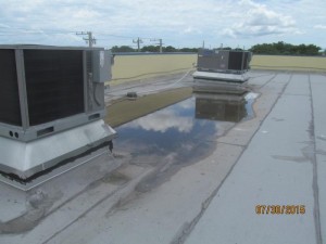
U.S. Forensic was hired to determine the cause and extent of damage to a 2-story commercial building that was constructed in 2014. The building was constructed of 8” thick concrete floor and roof slabs and concrete masonry unit (CMU) walls. It was reported to U.S. Forensic that the second story floor and roof slabs were cracked and severely deflected downward at the middle of the building. The owner indicated that he first observed a problem when the finishes of a non-bearing partition wall in between the second story and roof slabs had developed cracks at a doorway. He indicated that the cracks in the underside of the roof slab were then observed. The owner reported that the floor deflection had been an issue since the system was constructed and that he suspected that it was design error. He indicated that there was significant water ponding on the roof where the underlying slab had deflected.
Evaluation & Findings
Our work to complete this assignment was performed by William A. Yanko, Ph.D., P.E. Dr. Yanko reviewed permit documents, structural drawings, and performed a thorough site inspection. He also performed several hand calculations and computer generated models to assess the expected performance of the concrete slabs. U.S. Forensic generated several different computer simulations for assessing the slab design to determine the anticipated deflection, code-required rebar, and expected crack pattern. This type of system can normally be designed using hand calculations. However, our generation of a computer model was intended to simulate the field conditions more precisely and provide the client (who possibly does not have an engineering education) with graphical images that were more easily understandable. The software utilized a 3-D finite element analysis with the walls and floor modeled with properties indicative of those specified in the structural drawings. Live and dead service loads were applied to slab surfaces in the models. The pattern of cracking observed in the field and within the models conformed to what was expected from basic engineering mechanics for this type of system. The crack pattern was clearly consistent with what is commonly known as yield line theory, where cracks form at maximum flexural moment locations (hinges). Yield line theory is not a new methodology for examining slabs (first presented in the early 1920’s and applied to concrete slabs in the early 1960’s). The theory is commonly presented in an introductory concrete design class (normally in the junior year of an undergraduate engineering education). However, simple field examples such as these remind engineers that inclusion of basic theories is important in an engineering education. Furthermore, a computer is likely not available for usage during field inspections. Diagnosis of a problem is often based solely on the expertise of the investigator, not the output from a computer model. Dr. Yanko’s findings were as follows:
- The physical evidence observed at the site and the information in the original construction drawings indicated that the concrete slab design for the roof and floor was insufficient for the span. The observed cracks and deflection in the slabs were the result of inadequate design.
- The physical evidence observed at the site indicated that the inferior structural design caused a life-safety issue and the building should not be occupied until a proper retrofit is performed.
- Our design calculations for the concrete slabs indicated that the thickness and reinforcement specified for the floor slab was insufficient for the service and strength conditions.
- The physical evidence observed at the site indicated there was a steel column on the first story at the middle of the building that appeared to be load bearing. The structural element was not on the permitted structural drawings and there was suspected punching shear issues in the second floor slab around the column bearing location.
- Based on the clearly inadequate design of the concrete slabs, we recommend that a full structural review be performed of the building to identify deficiencies in the construction drawings.
Photographs & Computer Models
- Ponded water on roof
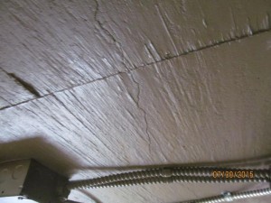
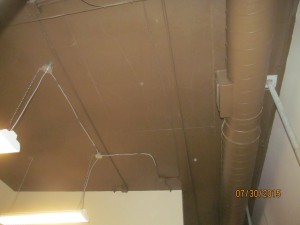
- Cracks in the underside of roof slab
- Extensive cracking on the bottom of the roof slab near mid-span (zone of maximum flexure)
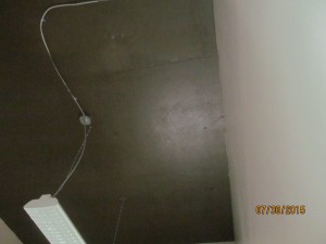
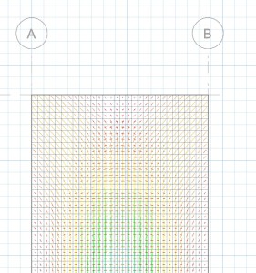
- Cracks on the bottom of the roof slab rotated 45 degrees toward corner of building (consistent with yield-line theory)
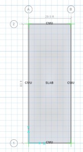
- Model Input of Roof Slab
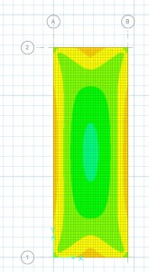
- Bottom Surface Stress of Roof Slab
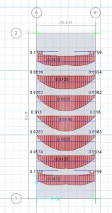
- Required Rebar for Roof Slab (East-west direction only)
- Crack Orientations and Widths of Roof Slab
